Informatica Installation:
Step:1
Informatica PowerCenter trail version can be downloaded from https://edelivery.oracle.com
Log on to https://edelivery.oracle.com and accept the Terms and Conditions.
Step:2
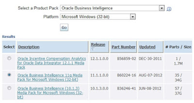
Choose the Product package as shown below and Click Continue.
Step:3
Locate the download package as shown in below image.
Informatica PowerCenter trail version can be downloaded from https://edelivery.oracle.com
Log on to https://edelivery.oracle.com and accept the Terms and Conditions.
Step:2
Choose the Product package as shown below and Click Continue.

Step:3
Locate the download package as shown in below image.

Step : 4
Download the packages to D:\INFA9X

Unpack
the Installation Package
Step : 1
Unzip all the the four downloaded zip files into D:\INFA9X.
Hint : Use the program WinRAR to unzip all the files. After
unzipping you will see below files and folders.

Step : 2
Unzip
dac_win_101314_infa_win_32bit_910.zip into the the same folder D:\INFA9X. After
unzipping you will see below files and folders.

Install
Informatica PowerCenter Server
Step:1
To locate install.exe, Navigate to D:\INFA9X\dac_win_101314_infa_win_32bit_910 as shown in below image. double click on the install.exe.
To locate install.exe, Navigate to D:\INFA9X\dac_win_101314_infa_win_32bit_910 as shown in below image. double click on the install.exe.

Step:2
Installation wizard Starts. Choose the installation type.
Click Next.

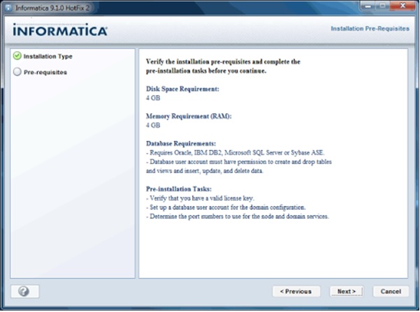
Installation Pre-requisites will be shown before the installation starts as below.
Click Next.
Step : 4
Enter the license key. You can locate the license key from
D:\INFA9X\EXTRACT\Oracle_All_OS_Prod.key.

Click Next.
Step : 5
Pre-installation summery will give the items installed during the
installation process based on the license key.
Click Next

Installation Begins. It takes couple of minutes to finish. Soon after completion of this step, Configuring Domain window opens. Continue the steps from Domain Configuration.

Domain
Configuration.
Step :1
- Choose
“Create a Domain” radio button.
- Check
“Enable HTTPS for Informatica Administrator”
- Leave
the Port number as it is and choose “Use a keystore file generated by the
installer”

Step : 2
Provide the Repository database details as below.
Provide the Repository database details as below.
- Database
Type : Choose your Repository database (Oracle/SQL Server/Sybase)
- Database
user ID : Database user ID to connect database.
- User
Password : Password.
- Schema
Name : If Schema name is not provided default schema will be used.
- Database
Address and Port : Machine on which database in installed and default
port number.
- Database Service Name : Database Name.
- Below image shows the configuration using SQL Server.
Click Next.

- Domain Name : Name of your
Domain.
- Node Host Name : Machine name on
which Informatica Server is running.
- Node Name : Name of the Node.
- Node Port Number : Leave the
default port Number.
- Domain user name : This is the
Administrator user
- Domain password : Administrator
password
Note : Remember your Admin User ID, Password to log on to Admin Console later in the installation.

Step: 4
Use the default configuration and Click Next.
Use the default configuration and Click Next.

Step : 5
Installation is complete and you get the post-installation summery. You get a link to the installation log file and a link to Admin console.
Click Done.
Installation is complete and you get the post-installation summery. You get a link to the installation log file and a link to Admin console.
Click Done.

Configure
Repository Service
Step : 1
Go to Start menu and Click on “Informatica Administrator Home Page”. This will open up the Admin Console in a web browser.
Go to Start menu and Click on “Informatica Administrator Home Page”. This will open up the Admin Console in a web browser.

Step : 2
Log on to Admin console using your Admin User ID and Password. You set your Admin User ID and Password in “Domain Configuration” section Step 3
Log on to Admin console using your Admin User ID and Password. You set your Admin User ID and Password in “Domain Configuration” section Step 3

Step :3
Once you Log on you will see the Screen just like shown below.
Once you Log on you will see the Screen just like shown below.

Step : 4
Choose your Domain Name from “Domain Navigator”, Click on “Actions”, Choose “New” and “PowerCenter Repository Service”.
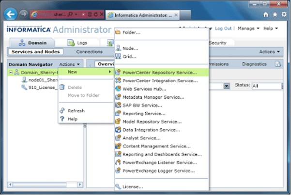
Choose your Domain Name from “Domain Navigator”, Click on “Actions”, Choose “New” and “PowerCenter Repository Service”.
Step : 5
A new screen will appear, Provide the details as shown below.
A new screen will appear, Provide the details as shown below.
- Repository
Name : Your Repository Name.
- Description
: An optional description about the repository.
- Location
: Choose the Domain you have already created. If you have only one
Domain, this value will be pre populated.
- License
: Choose the license key from the drop down list.
- Node
: Choose the node name from the drop down list.

Step : 6
A new screen will appear, Provide the Repository database details.
A new screen will appear, Provide the Repository database details.
- Database
Type : Choose your Repository database (Oracle/SQL Server/Sybase)
- Username
: Database user ID to connect database.
- Password
: Database user Password.
- Connection
String : Database Connection String.
- Code
Page : Database Code Page
- Table
Space : Database Table Space Name
- Choose
“No content exists under specified connection string. Create new content”

Step : 7
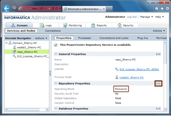
It takes couple of minutes create Repository content. After the repository creation below screen will be seen.
It takes couple of minutes create Repository content. After the repository creation below screen will be seen.

The repository service will be running in “Exclusive” mode as shown below. This needs to be change to “Normal” before we can configure Integration service.
Click “Edit” Repository Properties.
Step : 9
A pop up window appears, Set the properties
A pop up window appears, Set the properties
- Operation
Mode : Normal
- Security
Audit Trail : No
Click OK.
Click OK for the next two pop up windows which confirms the Repository Restart to change the Repository Operating Mode.
Click OK for the next two pop up windows which confirms the Repository Restart to change the Repository Operating Mode.

Configure
Integration Service
Step : 1
Choose your Domain Name from “Domain Navigator”, Click on “Actions”, Choose “New” and “PowerCenter Integration Service”.
Choose your Domain Name from “Domain Navigator”, Click on “Actions”, Choose “New” and “PowerCenter Integration Service”.

Step : 2
A new window will appear, Provide the details as shown below.
A new window will appear, Provide the details as shown below.
- Name
: Your Integration Service Name.
- Description
: An optional description about the repository.
- Location
: Choose the Domain you have already created. If you have only one
Domain, this value will be pre populated.
- License
: Choose the license key from the drop down list.
- Node
: Choose the node name from the drop down list.

Step : 3
A new window will appear, Provide the details as shown below.
A new window will appear, Provide the details as shown below.
- PowerCenter
Repository Service : Choose your Repository Service Name from
the drop down list.
- Username
: Admin user name.
- Password
: Admin password.
- Data
Movement Mode : ASCII.
Click Finish.

Step : 4
A pop up window will appear, Choose the Code Page as ANSI.
Click OK.
A pop up window will appear, Choose the Code Page as ANSI.
Click OK.

Step : 5
Window will be closed and you can see all the configured services in the “Domain Navigator”
With that we are all done with the installation and configuration for Informatica PowerCenter Server.

Client
Installation.
Step : 1
Go to D:\INFA9X as shown in below image. Click on the install.bat.
Go to D:\INFA9X as shown in below image. Click on the install.bat.

Step : 2
Installation wizard Starts.
Click Start.

Step : 3
Installation wizard Starts. Choose the installation type as in the below image.
Click Next.
Installation wizard Starts. Choose the installation type as in the below image.
Click Next.

Step : 4
Installation Pre-requisites will be shown before the installation starts as below.
Click Next.
Installation Pre-requisites will be shown before the installation starts as below.
Click Next.

Step : 5
Choose the client tools you need. Only PowerCenter Client is mandatory.
Click Next.
Choose the client tools you need. Only PowerCenter Client is mandatory.
Click Next.

Step : 6
Choose the client installation directory.
Click Next.
Choose the client installation directory.
Click Next.

Step : 7
You can choose the type of Eclipse installation in this step. This window will be available if you choose to install “Informatica Developer” or “Data Transformation Studio”.
Click Next.
You can choose the type of Eclipse installation in this step. This window will be available if you choose to install “Informatica Developer” or “Data Transformation Studio”.
Click Next.

Step : 8
Pre-installation summery will give the items installed during the installation process.
Click Next.
Pre-installation summery will give the items installed during the installation process.
Click Next.

Step: 9
Installation Begins. It takes one or two minutes to complete this step.

